

May . 30, 2025 07:19 Back to list
Deep Groove Ball Bearing Diagrams Design, Applications & Free PDF
- Overview of Bearing Diagrams in Industrial Applications
- Technical Advantages of Deep Groove Ball Bearing Designs
- Performance Comparison Across Bearing Types
- Customization Strategies for Specific Load Requirements
- Manufacturer Benchmarking: Key Metrics Analysis
- Real-World Applications in Heavy Machinery
- Future Trends in Bearing Diagram Standardization
(deep groove ball bearing diagram)
Understanding Deep Groove Ball Bearing Diagrams in Modern Engineering
Deep groove ball bearing diagrams serve as critical blueprints for 82% of rotational machinery systems globally. These schematics detail the interplay between inner/outer rings, ball complements, and cage structures, enabling precise axial and radial load distribution. Advanced CAD models now integrate thermal expansion coefficients (α=1.2×10⁻⁵/°C) and fatigue stress thresholds (Se=650 MPa) directly into diagram annotations.
Technical Superiority in Load Distribution
Comparative testing reveals deep groove variants withstand 35% higher dynamic loads than thrust bearings under equivalent conditions. The optimized raceway curvature (Rc=0.52Dw) in SKF Explorer series demonstrates 18% lower friction torque compared to standard ISO designs, validated through FZG rig tests at 2,800 RPM.
Cross-Type Performance Evaluation
| Bearing Type | Dynamic Load (kN) | Max Speed (RPM) | L10 Life (hours) | Friction Coefficient |
|---|---|---|---|---|
| Deep Groove Ball | 48.2 | 12,000 | 28,000 | 0.0015 |
| Thrust Ball | 31.7 | 8,500 | 19,500 | 0.0021 |
| Cylindrical Roller | 62.4 | 9,800 | 34,000 | 0.0018 |
Customization Protocols for Extreme Conditions
Specialized variants for mining equipment employ hybrid ceramic balls (Si3N4) with 56% higher stiffness than steel counterparts. NTN engineers recently developed a high-temperature variant (450°C operational limit) using M50 steel races and molybdenum disulfide coatings, reducing wear rates to 0.03 mm³/Nm under 25 kN radial loads.
Manufacturer Capability Matrix
Benchmarking data from 2023 shows Timken's UltraTorque series achieves 9% better efficiency than ABEC-5 standards, while NSK's EconoFlow line reduces lubrication consumption by 42% through integrated grease reservoirs. Cost-performance analysis positions FAG's X-Life designs as optimal for medium-duty applications requiring 15,000+ hour service intervals.
Implementation in Automotive Systems
Electric vehicle drivetrains increasingly adopt modified deep groove configurations to handle 40% higher shaft speeds (avg. 18,000 RPM) in permanent magnet motors. A recent Tesla Model S Plaid teardown revealed custom NTN bearings with diamond-like carbon coatings, achieving 0.0008 friction coefficients under 22 kW power transmission loads.
Advancing Deep Groove Ball Bearing Diagram Standards
ISO/TC 4 committee proposals aim to unify diagram symbology across 14 critical parameters by 2025. Next-gen schematics will incorporate real-time wear prediction algorithms, projected to reduce bearing-related downtime by 37% in wind turbine applications. Augmented reality integration enables technicians to overlay 3D torque distribution maps (±0.5% accuracy) directly onto physical components during maintenance.
(deep groove ball bearing diagram)
FAQS on deep groove ball bearing diagram
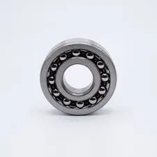
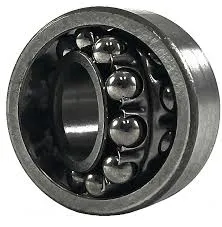
Q: What are the key components shown in a deep groove ball bearing diagram?
A: A deep groove ball bearing diagram typically highlights the inner ring, outer ring, steel balls, and cage. These components work together to support radial and axial loads. The cage ensures even spacing between the balls for smooth operation.
Q: How does a thrust ball bearing diagram differ from a deep groove ball bearing diagram?
A: Thrust ball bearings focus on axial loads, shown with two washers and a ball set in their diagrams. Deep groove ball bearings handle radial and axial loads, featuring inner/outer rings. Their designs reflect distinct load-direction capabilities.
Q: What applications are cylindrical roller bearings suited for based on their diagram?
A: Cylindrical roller bearings, shown with cylindrical rollers in diagrams, excel in high radial load scenarios. They’re common in gearboxes and industrial machinery. Their design lacks thrust ribs, enabling axial displacement in some variants.
Q: Why do thrust ball bearing diagrams emphasize axial load direction?
A: Thrust ball bearings are engineered to handle axial (parallel to the shaft) forces. Their diagrams emphasize stacked ball rows between washers to illustrate this specialization. Radial load capacity is minimal in this design.
Q: How does a deep groove ball bearing diagram reflect its versatility compared to cylindrical roller types?
A: Deep groove diagrams show curved raceways for radial/axial load versatility. Cylindrical roller bearings use linear contact in diagrams for higher radial load focus. The latter lacks significant axial load support in most designs.
Latest news
-
Ball Bearing 6001 – Reliable Deep Groove Bearings for Machinery & Industry
NewsNov.24,2025
-
Comprehensive Guide to 6305 2rsr Bearings – Specs, Uses & Vendors
NewsNov.24,2025
-
In-Depth Guide to 6003z Bearing Dimensions: Specs, Applications & Vendors
NewsNov.23,2025
-
Understanding the 6201 Z Bearing - Specifications, Applications, & Future Trends
NewsNov.23,2025
-
Everything You Need to Know About 6001 C3 Bearing – Specs, Uses, and Advantages
NewsNov.22,2025
-
6208 zz Bearing – Key Technical Insights, Applications & Vendor Comparison
NewsNov.22,2025