Jul . 31, 2024 12:27 Back to list
Designing a Deep Groove Ball Bearing Model in SolidWorks for Engineering Applications and Analysis
Designing Deep Groove Ball Bearings in SolidWorks
Deep groove ball bearings are critical components in various mechanical systems, providing smooth rotational motion and supporting radial and axial loads. In the context of engineering design, using software such as SolidWorks can significantly streamline the creation and modification of these bearings. This article explores how to effectively design deep groove ball bearings in SolidWorks, along with some considerations for functionality and application.
Understanding Deep Groove Ball Bearings
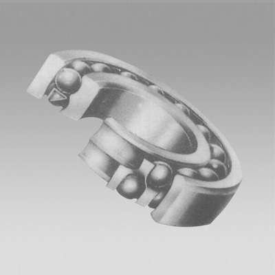
Deep groove ball bearings are characterized by their simple, robust design, which incorporates an inner and outer ring, a cage, and balls. The deep groove allows for larger load capacities and greater stability, making them suitable for high-speed applications. Their versatility means they can be found in everything from household appliances to industrial machinery.
Setting Up in SolidWorks
To begin designing a deep groove ball bearing in SolidWorks, you’ll first want to familiarize yourself with the software's interface and tools. A new part can be created by selecting “New” from the File menu. Choose the “Part” option, as this is where you will draft the bearing components.
1. Creating the Outer and Inner Rings Start by sketching the outer ring of the bearing. Use the circle tool to create two concentric circles, representing the outer diameter and the groove. The groove depth can be defined by offsetting the inner circle inward. After completing the sketch, utilize the “Extrude Boss/Base” feature to give the ring its thickness. Repeat this process for the inner ring, ensuring accurate alignment.
2. Designing the Balls Use a spherical shape to model the balls that roll between the rings. You can create a new part for the balls or use the Copy function if you're maintaining the size and design parameters. The Revolve Boss/Base feature is ideal for creating these spherical shapes.
deep groove ball bearing solidworks

3. Adding the Cage The cage holds the balls in place to prevent overcrowding and ensure even distribution during rotation. This can be designed using the “Loft” or “Sweep” features from various sketched profiles. Pay attention to the spacing between the balls, as it is crucial for the proper functioning of the bearing.
4. Assembly Once all components are designed, you can begin assembling them. Utilize the “Assembly” feature in SolidWorks to place the inner and outer rings, balls, and cage together. The assembly tool allows you to apply mates to define how parts fit together, ensuring that everything rotates as intended.
Analysis and Testing
After assembling your deep groove ball bearing, SolidWorks offers various simulation tools that help evaluate performance under specified loads and speeds. The “Simulation” add-on can be particularly useful in analyzing stress, displacement, and overall durability in realistic conditions. Set up simulations to reflect real-world usage, which will provide insights into potential design flaws and areas for improvement.
Conclusion
Designing deep groove ball bearings in SolidWorks merges the principles of mechanical engineering with advanced digital tools. With the ability to create detailed designs, simulate real-world performance, and iterate quickly through design changes, SolidWorks empowers engineers and designers to innovate effectively. By understanding the key components and utilizing the software’s capabilities, one can successfully create functional and efficient deep groove ball bearings that meet the demands of various applications in both consumer and industrial markets.
In summary, adopting a methodical approach to designing these bearings not only enhances the design process but also leads to improved performance outcomes in the final product.
Latest news
-
Common Failures in Thrust Ball Bearings and Solutions
NewsAug.22,2025
-
How Tapered Roller Bearings Can Take Shock Loads
NewsAug.22,2025
-
Angular Bearings in High-Precision Spindles
NewsAug.22,2025
-
The Impact of Misalignment on Cylindrical Roller Bearing Performance
NewsAug.22,2025
-
The Role of Cage Design in Deep Groove Ball Bearing Durability
NewsAug.22,2025
-
The Impact of Material Quality on Machinery Bearings’ Lifespan
NewsAug.22,2025
