Dec . 04, 2024 14:51 Back to list
deep groove ball bearing solidworks
Understanding Deep Groove Ball Bearings in SolidWorks
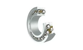
Deep groove ball bearings are essential components widely used in various mechanical systems, providing efficient rotation and reducing friction. They are designed to accommodate both radial and axial loads, making them suitable for various applications, from household appliances to industrial machinery. Using SolidWorks, an advanced 3D CAD software, engineers can design and analyze these bearings effectively, ensuring optimal performance in their intended applications.
Designing Deep Groove Ball Bearings in SolidWorks
When designing a deep groove ball bearing in SolidWorks, the first step is to define the bearing's specifications, which include dimensions such as bore diameter, outer diameter, width, and materials used. Designers typically refer to industry standards like ISO or ABEC (Annular Bearing Engineers' Committee) to determine the requisite dimensions and tolerances. SolidWorks allows users to create detailed 3D models that accurately reflect these specifications.
The design process begins with sketching the basic geometry of the inner and outer races. The inner race, where the ball rests, must fit snugly on the shaft, while the outer race is often housed in a bearing seat. SolidWorks features powerful sketching tools enabling precise modifications and adjustments in real time, which is essential for ensuring that the bearing will function correctly.
Once the races are sketched, the next step involves creating the ball elements. A deep groove ball bearing typically contains several steel or ceramic balls situated between the two races. These balls facilitate smooth rotation, reducing friction and wear. Using SolidWorks, designers can create a pattern to replicate the balls around the inner race, ensuring they are evenly distributed.
Simulation and Analysis
deep groove ball bearing solidworks

One of the most powerful features of SolidWorks is its ability to perform simulations. After creating the model, engineers can analyze how the bearing will perform under various load conditions. SolidWorks Simulation tools allow users to apply forces, rotational speeds, and constraints to analyze stress distributions and deformation. This analysis is critical because it helps predict potential failure points, ensuring reliability and longevity in real-world applications.
For example, engineers can simulate how the bearing behaves with radial loads versus axial loads, which is vital for applications where the bearing will experience both types of forces. Understanding these dynamics allows for better material selection and design adjustments, optimizing the bearing's performance.
Finalization and Production
Upon successful simulation and validation of the design, the next step is preparing the bearings for production. SolidWorks provides tools for creating detailed technical drawings, including assembly instructions and part specifications, ensuring that manufacturers have all the necessary information to produce the components accurately. These drawings also aid in quality control during the manufacturing process.
Moreover, SolidWorks integrates with various manufacturing technologies, enabling direct exportation of designs to CNC machines or 3D printers. This streamlines the transition from design to production, reducing lead times and improving efficiency.
Conclusion
In conclusion, deep groove ball bearings play a crucial role in many mechanical systems, and designing them effectively requires precision and advanced tools. SolidWorks is an invaluable platform for engineers, providing the functionalities necessary to create, simulate, and prepare these bearings for production. By leveraging the capabilities of SolidWorks, engineers can ensure that their deep groove ball bearings meet the highest standards of performance and reliability, ultimately contributing to the success of the mechanical systems in which they are used.
Latest news
-
Grooved Ball Bearing Design and Functionality
NewsJun.04,2025
-
Concrete Mixer Bearing Load Capacity Testing
NewsJun.04,2025
-
6004 Bearing Dimensions in Robotic Joint Designs
NewsJun.04,2025
-
Advantages of Single-Row Deep Groove Ball Bearings
NewsJun.04,2025
-
Applications of Deep Groove Ball Bearings in Automotive Systems
NewsJun.04,2025
-
Innovations in Bearing Pressing Machine Design
NewsJun.04,2025
