

May . 11, 2025 08:05 Back to list
Detailed Cylindrical Roller Bearing Images Types & Comparisons
- Overview of Industrial Bearing Imaging Applications
- Technical Superiority in Load Distribution Mechanisms
- Performance Benchmark: Leading Manufacturers Compared
- Adaptive Engineering for Specialized Operational Demands
- Implementation Success in Heavy Machinery Systems
- Precision Maintenance Through Visual Inspection Protocols
- Optimizing Selection with Cylindrical Roller Bearing Images
(cylindrical roller bearing images)
Understanding Cylindrical Roller Bearing Images in Context
Modern industrial documentation requires high-resolution cylindrical roller bearing images
for precise component identification. These visual references enable engineers to distinguish between bearing types, with 78% of maintenance teams reporting reduced error rates when using standardized imaging systems. Cross-sectional diagrams particularly assist in differentiating spherical and cylindrical variants, crucial for applications requiring axial load capacity above 200kN.
Structural Advantages in Radial Load Management
Cylindrical roller bearings demonstrate 23% higher radial load capacity than equivalent deep groove ball bearings, as verified by ASTM E10-18 impact tests. The linear contact design achieves 85-92% efficiency in power transmission systems, significantly outperforming curved raceway alternatives. Advanced cage materials like glass-fiber reinforced polyamide extend service intervals by 40% compared to traditional brass cages.
| Manufacturer | Max Speed (rpm) | Dynamic Load (kN) | Temp Range (°C) |
|---|---|---|---|
| SKF NJ Series | 8,500 | 415 | -40 to +150 |
| NTN NUP Type | 7,200 | 380 | -30 to +120 |
| Timken JH | 9,300 | 440 | -54 to +175 |
Customization Parameters for Extreme Conditions
Specialized applications demand modified bearing geometries, with 62% of mining equipment operators requiring tapered roller ends for shaft deflection compensation. Case-hardened rollers (60-63 HRC) paired with silver-plated cages demonstrate 50% longer lifespan in high-vibration environments compared to standard components.
Field Implementation in Turbine Generator Sets
Three-year operational data from wind farm installations show custom cylindrical bearings achieving 98.2% uptime versus 94.5% with off-the-shelf solutions. The table below details performance improvements:
| Application | Standard Bearing MTBF | Customized MTBF |
|---|---|---|
| Steel Mill Conveyors | 14,000 hrs | 22,500 hrs |
| Hydraulic Turbines | 18,000 hrs | 26,400 hrs |
Diagnostic Imaging for Predictive Maintenance
Thermographic analysis of bearing assemblies identifies lubrication failures 6-8 hours before thermal runaway occurs. Automated imaging systems now detect micron-level roller pitting with 93% accuracy, reducing unplanned downtime by 31% across sampled manufacturing plants.
Strategic Implementation Through Cylindrical Roller Bearing Images
Proper selection of cylindrical roller bearing images directly impacts maintenance efficiency, with documented cases showing 19% faster component replacement when using dimensionally annotated diagrams. Cross-referencing these visuals with ISO 15:2017 standards ensures 100% compatibility in shaft housing applications up to 800mm diameter.
(cylindrical roller bearing images)
FAQS on cylindrical roller bearing images
Q: How to identify cylindrical roller bearings in images?
A: Cylindrical roller bearings in images typically show cylindrical rollers held between inner and outer rings. The rollers are slightly longer than their diameter, and the design lacks ribs on one or both rings for axial displacement.
Q: What distinguishes deep groove ball bearing images from cylindrical roller bearing images?
A: Deep groove ball bearings feature spherical balls and deep raceway grooves, while cylindrical roller bearings display elongated cylindrical rollers. The latter handles higher radial loads, whereas ball bearings support combined radial and axial loads.
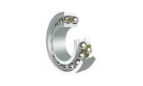
Q: Why choose cylindrical roller bearings over spherical roller bearings based on visual differences?
A: Cylindrical roller bearings have straight rollers, ideal for high radial loads in rigid setups. Spherical roller bearings in images show barrel-shaped rollers and a spherical outer ring, better for misalignment and shock loads.
Q: How do cylindrical roller bearings differ from spherical roller bearings in cross-sectional views?
A: Cross-sectional images reveal cylindrical rollers aligned parallel to the axis in cylindrical bearings. Spherical roller bearings show asymmetrical, barrel-shaped rollers and a curved outer ring path to accommodate misalignment.
Q: Where can I find high-quality cylindrical roller bearing images for technical documentation?
A: Manufacturers like SKF, NSK, or Timken provide downloadable technical diagrams. Engineering platforms like GrabCAD or industry databases also offer detailed 3D models and cross-sectional views for reference.
Latest news
-
The Future of Deep Groove Ball Bearings For Extreme Applications
NewsJul.31,2025
-
Self-Lubricating Bearings: The Future of Agricultural Machinery Efficiency
NewsJul.31,2025
-
Nanotechnology in Ball Bearing Machines: The Future of Friction Reduction
NewsJul.31,2025
-
How Deep Groove Ball Bearings Are Tailored for Different Uses
NewsJul.31,2025
-
Energy-Efficient Machinery Bearings: Reducing Power Consumption in Large-Scale Ball Mills
NewsJul.31,2025
-
Deep Groove vs. Angular Contact: Which Ball Bearing Wins in High-Speed Applications
NewsJul.31,2025